Does the stepper motor have an encoder? How to add an encoder to the stepper motor
Working principle of stepper motor
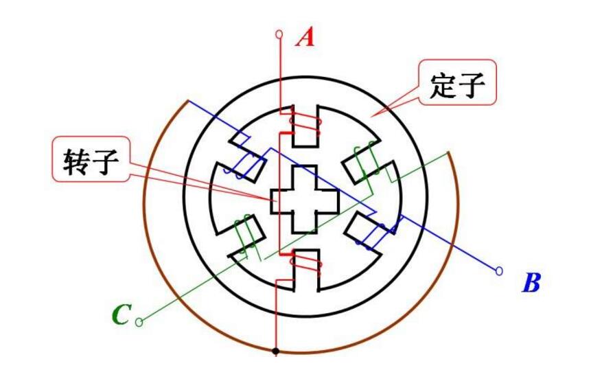
When current flows through the stator winding, the stator winding generates a vector magnetic field. The magnetic field will drive the rotor to rotate by an angle, so that the pair of magnetic field directions of the rotor are consistent with the magnetic field directions of the stator. When the vector magnetic field of the stator rotates by an angle. The rotor also rotates an angle with the magnetic field. Each time an electric pulse is input, the motor rotates an angle to move forward. Its output angular displacement is proportional to the number of input pulses, and the speed is proportional to the pulse frequency. Change the sequence of winding energization and the motor will reverse. Therefore, the number of pulses, frequency and the energization sequence of each phase winding of the motor can be used to control the rotation of the stepper motor.
All types of motors that are usually seen have iron cores and winding coils inside. Windings have resistance, energization will produce losses. The loss is proportional to the square of the resistance and the current. This is what we often call copper loss. If the current is not a standard DC or sine wave, harmonic losses will also occur; iron cores have hysteresis The eddy current effect also produces loss in an alternating magnetic field. Its magnitude is related to the material, current, frequency, and voltage, which is called iron loss.
Copper loss and iron loss will be manifested in the form of heat, thus affecting the efficiency of the motor. Stepper motors generally pursue positioning accuracy and torque output, with relatively low efficiency, relatively large currents, and high harmonic components. The frequency of current alternation also changes with the speed. Therefore, stepping motors generally have heat generation, and the situation is more common. The AC motor is serious.
Three stepper motor circuit diagrams
Circuit diagram 1:
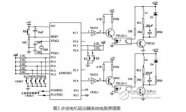
RL1 to RL4 in Figure 3 are the internal resistances of the windings, and the 50Ω resistance is an external resistance that acts as a current limiter and is also an element that improves the loop time constant. D1~D4 are freewheeling diodes, which make the back electromotive force generated by the motor windings attenuate through the freewheeling diodes (D1~D4), thus protecting the power tube TIP122 from damage.
A 200μF capacitor is connected in parallel with a 50Ω external resistor, which can improve the leading edge of the current pulse injected into the stepper motor winding and improve the high frequency performance of the stepper motor. The 200Ω resistor in series with the freewheeling diode can reduce the discharge time constant of the loop, make the trailing edge of the current pulse in the winding steeper, and the current fall time becomes smaller, and it also plays a role in improving the high-frequency working performance.
Circuit diagram two:
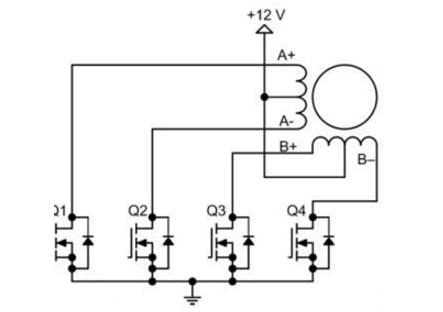
The driving circuit of a bipolar stepping motor is shown in the figure, it will use eight transistors to drive two sets of phases. The bipolar drive circuit can drive four-wire or six-wire stepper motors at the same time. Although four-wire motors can only use bipolar drive circuits, it can greatly reduce the cost of mass production applications. The number of transistors in a bipolar stepping motor drive circuit is twice that of a unipolar drive circuit. The four lower transistors are usually directly driven by a microcontroller, and the upper transistor requires a higher cost upper drive circuit. The transistor of the bipolar drive circuit only needs to bear the motor voltage, so it does not need a clamp circuit like the unipolar drive circuit.
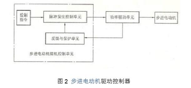
The stepping motor cannot be directly connected to the power frequency AC or DC power supply to work, but must use a dedicated stepping motor driver, as shown in Figure 2, which consists of a pulse generation control unit, a power drive unit, and a protection unit. The two units enclosed by the dashed line in the figure can be controlled by a microcomputer. The drive unit is directly coupled with the stepper motor, and can also be understood as the power interface of the stepper motor microcomputer controller.
Circuit diagram three:
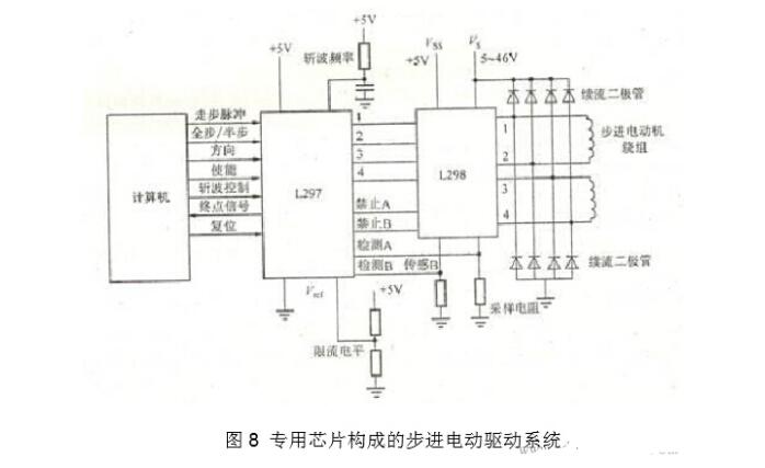
Figure 8 is a stepping motor drive system with constant current chopping function using L297 (a dedicated chip for ring distributor) and L298.
Does the stepper motor have an encoder
The stepper motor has no encoder. If you want to add an encoder to the stepper motor, you can extend the stepper motor with two shafts, and add an encoder on the rear shaft.
The stepping motor is the executive part. The encoder belongs to the feedback system. The encoder is used with the stepping motor and its operation is controlled by PLC. According to the principle, the PLC sends pulse instructions to the stepper driver, and the driver provides the corresponding current to the stepper motor to make it run. When the encoder detects that the stepper motor runs to the position it needs to reach, it will feedback a signal to the PLC and the PLC installs The feedback signal stops sending pulse signals to the stepper driver. When the stepper motor has no electric current to provide current, it will of course stop running immediately. (Servo motor is such a device), in fact, the encoder will continuously feedback the current position to the PLC, and the PLC will compare the feedback value with the target value to adjust the angle of rotation of the rotor.
Of course, will it stop steadily? After stopping, is it the position you want? This depends on whether the motor has a braking device? Of course, if running at low speed, the general feed accuracy can be satisfied.
There is also a way to calculate the number of pulses required for the stepper motor feed in advance, and then program it with PLC, run so many pulses, the stepper motor stops, the encoder feedbacks the motor position at this time, forming a semi-closed loop control. In addition to high-speed positioning, the PLC program can set the motor to decelerate when the position is approaching, which can meet the positioning accuracy.
How to add encoder to stepper motor
The stepper motor encoding is a bit tasteless, which is a waste of resources; because the stepper motor cannot respond in real time, there must be an acceleration and deceleration process;
Example: Use an Oriental stepping motor with a harmonic reducer, a reduction ratio of 100:1, step angle: 0.0072°, want to add an encoder to prevent lost steps, etc., the following is the method:
Answer: In principle, it is also possible to install a motor at one end of the lead screw and an encoder at the other end. However, this will be affected by the accuracy of the reducer, and misjudgment of lost steps may occur. It is best to add an encoder with a double-output shaft motor. The encoder is added at the back of the motor, and the servo motor does this, unless you use it for special use or conditional restrictions (no double-output shaft). Generally, 2500 lines can be processed, and too high number of lines is a waste.
In addition, the resolution of the encoder is roughly the same as the resolution of your stepping motor. If the subdivision on the drive is very high and you only want to detect whether it is lost, the resolution of the encoder only needs to be the same or slightly higher than the resolution before subdivision.
The meaning of stepping motor plus encoder
Although the stepping motor is a device that can be accurately controlled, it is open-loop, and an encoder is required to achieve closed-loop feedback control; and the stepping motor can be measured out of step and rotating or moving speed for dynamic speed control. For this statement, I think it is understandable that the first open-loop control requires an encoder to achieve closed-loop feedback, because I am using it, occasionally because of the poor wire connection of the stepper motor, which leads to stepping. The motor is not working properly. For the second point, the speed control of the stepper motor is not very necessary, because the speed can be adjusted by controlling the pulse frequency of the stepper motor, and it is really unnecessary to use external feedback.